With its outstanding heat dissipation performance, good mechanical strength, and unrestricted airflow direction, it is widely used in electronic devices, LED lighting, motors, and other fields.
Additionally, we can customize the shape and size of the pin fins of the heat sink according to customer requirements to meet various heat dissipation needs.
Specifications of pin fin heat sink
Alloys: 1060, 1070, 6061, 6063
Length: 15 - 200 mm (customizable)
Width: 15 - 250 mm
Height: 10 - 30 mm
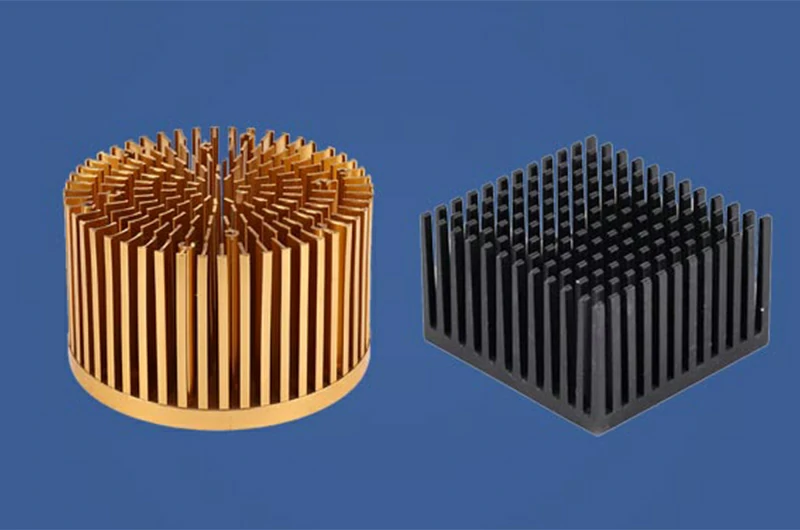
Pin Fin Shapes: Square, cylindrical, elliptical, trumpet (inclined)
Recommended Air Velocity: 0–800 LFM (0–4 m/s)
Manufacturing Processes: Cold forging, extrusion, stamping
Standards: IEC 60287-1-1, IEC 60287-1-2, ASTM D5450, GB/T 11403, IATF 16949
Certifications: RoHS, CE, SGS, ISO, TUV SUD, UL
Services provided by Mastar Metal
For bulk or repeat orders, Mastar Metal offers the most competitive prices or waives mold fees.
Mastar Metal provides customization services with the ability to manufacture special shapes and large heat sinks.
Mastar Metal offers thermal analysis testing services to help you evaluate the performance of heat sinks.
Mastar Metal has ample inventory and a variety of mold sizes, providing quick delivery services.
Mastar Metal provides samples and shipping.
Strict dimensional tolerances to meet your high requirements.
We also provide extrusion heat sink and other heat sink products, for additional options on design and processing, see our heat sink solutions.
Popular stock sizes for pin fin heat sink

Dimensions of round pin fin heat sink
Thermal resistance data is for reference only and may vary in practice.
For thermal analysis or to determine actual thermal resistance, please contact us.Quick Quote
| Width (mm) | Length (mm) | Height (mm) | Thermal resistance (°C/W) - Natural Convection | θSA (°C/W) at 0.5 m/s (100 LFM) | θSA (°C/W) at 1.0 m/s (200 LFM) | θSA (°C/W) at 2.0 m/s (400 LFM) |
| 15 | 15 | 10 | 14.14 | 9.66 | 7.9 | 6.94 |
| 15 | 15 | 15 | 9.32 | 6.37 | 5.24 | 4.64 |
| 17 | 17 | 10 | 13.01 | 9.03 | 7.47 | 6.6 |
| 17 | 17 | 15 | 8.67 | 6.03 | 5.01 | 4.46 |
| 19 | 19 | 15 | 6.55 | 4.38 | 3.56 | 3.12 |
| 23 | 23 | 10 | 7.61 | 5 | 4 | 3.45 |
| 23 | 23 | 15 | 4.95 | 3.25 | 2.61 | 2.28 |
| 27 | 27 | 15 | 3.94 | 2.55 | 2.03 | 1.75 |
| 30 | 30 | 10 | 19.1 | 8.07 | 5.12 | 3.35 |
| 30 | 30 | 30 | 9.9 | 3.23 | 2.16 | 1.53 |
| 35 | 35 | 10 | 4.15 | 2.59 | 1.98 | 1.66 |
| 35 | 35 | 15 | 2.7 | 1.66 | 1.27 | 1.07 |
| 40 | 40 | 10 | 14.6 | 5.24 | 3.19 | 2 |
| 40 | 40 | 30 | 6.89 | 2.11 | 1.36 | 0.94 |
| 50 | 50 | 10 | 11.8 | 3.99 | 2.41 | 1.49 |
| 50 | 50 | 30 | 5.33 | 1.54 | 0.97 | 0.65 |
| 60 | 60 | 10 | 9.54 | 3.58 | 2.24 | 1.43 |
| 60 | 30 | 20 | 7.95 | 2.44 | 1.6 | 1.09 |
| 60 | 60 | 30 | 3.9 | 1.26 | 0.79 | 0.52 |
| 80 | 40 | 10 | 10.3 | 2.73 | 1.65 | 1.02 |
| 80 | 80 | 30 | 3.37 | 0.83 | 0.5 | 0.32 |
| 90 | 50 | 30 | 3.84 | 0.84 | 0.53 | 0.35 |
| 90 | 90 | 30 | 3.05 | 0.72 | 0.43 | 0.27 |
| 100 | 50 | 30 | 3.62 | 0.76 | 0.47 | 0.32 |
| 100 | 100 | 30 | 2.8 | 0.63 | 0.37 | 0.23 |
| 120 | 60 | 30 | 3.07 | 0.59 | 0.36 | 0.24 |
| 120 | 100 | 30 | 2.6 | 0.53 | 0.31 | 0.19 |
| 120 | 120 | 30 | 2.41 | 0.52 | 0.31 | 0.19 |
| 125 | 95 | 10 | 5.58 | 1.36 | 0.8 | 0.49 |
| 125 | 100 | 30 | 2.54 | 0.51 | 0.3 | 0.18 |
| 140 | 120 | 10 | 4.74 | 1.17 | 0.69 | 0.42 |
| 140 | 120 | 30 | 2.27 | 0.44 | 0.26 | 0.16 |
| 200 | 125 | 30 | 1.99 | 0.32 | 0.19 | 0.12 |
| 240 | 140 | 30 | 1.74 | 0.26 | 0.14 | 0.09 |
| 250 | 200 | 30 | 1.35 | 0.25 | 0.15 | 0.09 |
 Click to see all
  Click to collapse
Dimensions of oval pin fin heat sink
Can't find the right heat sink size? Please let us know your requirements, and we will customize it for you.Quick Quote
| Width (mm) | length(mm) | Height (mm) | Thermal resistance (°C/W) Natural Convection | θSA (°C/W) at 0.5 m/s(100 LFM) | θSA (°C/W) at 1.0 m/s(200 LFM) | θSA (°C/W) at 2.0 m/s(400 LFM) |
| 19 | 19 | 9.5 | 30.4 | 10.4 | 7.63 | 5.97 |
| 19 | 19 | 14.5 | 21 | 7.32 | 5.38 | 4.16 |
| 19 | 19 | 24.5 | 12.9 | 4.56 | 3.46 | 2.74 |
| 19 | 19 | 27.9 | 11.6 | 4.11 | 3.15 | 2.52 |
| 27 | 27 | 9.5 | 18.5 | 6.2 | 4.34 | 3.32 |
| 27 | 27 | 14.5 | 12.5 | 4.27 | 3.03 | 2.3 |
| 27 | 27 | 24.5 | 7.62 | 2.62 | 1.92 | 1.49 |
| 27 | 27 | 27.9 | 6.83 | 2.35 | 1.74 | 1.36 |
| 35 | 35 | 9.5 | 12 | 3.92 | 2.64 | 2.01 |
| 35 | 35 | 14.5 | 7.93 | 2.62 | 1.78 | 1.35 |
Popular types of pin fin heat sinks
- BGA heat sinks are designed for Ball Grid Array (BGA) packaged chips and are typically mounted on top of the chip.
- CLCC heat sinks are designed for Ceramic Leaded Chip Carrier (CLCC) packaged chips to provide heat dissipation.
- DIP heat sinks are designed for Dual Inline Package (DIP) chips to aid in heat dissipation, particularly on compact circuit boards.
- QFP heat sinks are designed for Quad Flat Package (QFP) chips to provide heat dissipation.
- LQFP heat sinks are a low-profile version of QFP heat sinks, suitable for space-constrained situations.
- LCC heat sinks are designed for Leadless Chip Carrier (LCC) packaged chips to provide heat dissipation.
- LGA heat sinks are designed for Land Grid Array (LGA) packaged chips, similar to BGA heat sinks, and are installed on top of the chip.
- TSOP heat sinks are designed for Thin Small Outline Package (TSOP) chips.

Advantages of pin fin heat sink
- Pin fin heat sinks consist of a large number of slender fins, significantly increasing the heat dissipation surface area.
- The compact design of pin fin heat sinks allows for easy installation in various electronic devices.
- Pin fin heat sinks are lightweight, adding no extra weight burden to electronic devices.
- Aluminum pin fin heat sinks exhibit good durability and corrosion resistance.
- The production process of pin fin heat sinks is mature, leading to relatively lower costs.
- Engineers can customize the size and shape of pin fin heat sinks according to specific application requirements.

Common issues with pin fin heat sink
How to optimize the performance of pin fin heat sink
- The higher the overall height, the larger the heat dissipation surface area.
- Higher pin fin density leads to a larger heat dissipation surface area.
- Larger-sized heat sinks have a larger heat dissipation surface area.
- Thicker base thickness results in better heat conduction performance of the heat sink.
- Larger pin fin diameters lead to a larger heat dissipation surface area.
- Different arrangements of fins affect factors such as heat dissipation surface area and airflow resistance.
- Dark-colored surfaces typically have a stronger ability to absorb and emit thermal radiation compared to light-colored surfaces.

How do we test the performance of a heat sink?
- Measure the thermal resistance data of the heat sink transferring heat generated by the heat source to the environment.
- Measure the noise levels of the heat sink under different operating conditions.
- Evaluate the heat dissipation effectiveness of the heat sink in terms of hot spots and overall heat dissipation.
- Assess the airflow resistance of the heat sink and select appropriate fans.

If you have any requirements regarding heat sink performance testing, please feel free to contact us. We look forward to working with you and providing high-quality services!Quick Quote
Installation methods for pin fin heat sinks
- Thermal adhesive: It's relatively simple and economical, with moderate thermal conductivity. However, long-term use may lead to failure.
- Thermal tape/foil: Offers high and reliable thermal conductivity but involves slightly more complex installation and higher costs.
- Special clamps: Provides sturdy and efficient installation but comes with higher costs and complexity, suitable for high-demand scenarios.
- Press-fit: Requires specialized equipment, high-cost, and suitable for situations with high demands on size and weight.
- Screw tightening: Requires screw holes, which may affect heat dissipation, suitable for larger and heavier heat sinks.
- Spring screws: Higher cost and complex installation, suitable for applications requiring vibration and impact cushioning.
- Through-hole mounting: Requires drilling holes, which may affect structural strength, suitable for situations requiring mounting on PCB boards.
Customer selection recommendation: Consider factors such as size, weight, performance requirements, cost, installation difficulty, and application environment comprehensively when choosing an installation method.